Earthing Transformers

An earthing transformer (neutral coupler) is a three-phase transformer connected to the power system to provide a neutral connection for earthing, either directly or via impedance.The earthing transformers may in addition supply a local auxiliary load. In cases where the neutral point of three phase system is not accessible like the system connected to the delta connected side of a electrical power transformer, an artificial
neutral point may be created with help of a zigzag connected earthing transformer.
More Information
An earthing transformer (neutral coupler) is a three-phase transformer connected to the power system to provide a neutral connection for earthing, either directly or via impedance.The earthing transformers may in addition supply a local auxiliary load. In cases where the neutral point of three phase system is not accessible like the system connected to the delta connected side of a electrical power transformer, an artificial neutral point may be created with help of a zigzag connected earthing transformer.
USES OF Earthing transformer
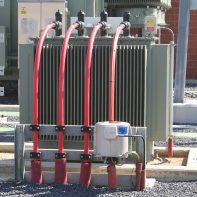
- Earthing transformers are usually oil immersed and may be installed outdoor. In cases where a separate reactor is connected between the transformer neutral and earth, the reactor and the transformer can be incorporated in the same tank.
- Ageing of the cellulose materials is then not a matter of concern. Regarding acceptable temperatures there are two aspects to consider.
- For currents with duration in the order of hours or more, temperatures that cause excessive gas development in the oil should be avoided.
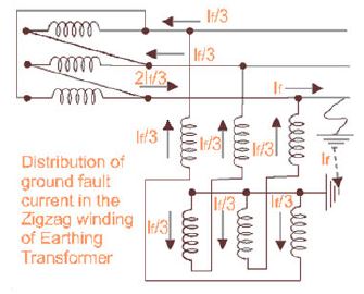
- The system earth fault protection relay may not be effective at low currents. For earthing transformers that carry continuous load because of a End point of all three winding ultimately connected together and forms a common neutral point. Now if any fault occurs at any of the phases in delta connected system, the zero sequence fault current has close path of circulating through earth as shown in the figure.
- In normal condition of the system, the voltage across the winding of the earthing transformer is 1/√3 times of rated per phase voltage of the system. But when single line to ground fault occurs on any phase of the system, as shown in the figure, zero sequence component of the earth fault current flows in the earth and returns to the electrical power system by way of earth star point of the earthing transformer. It gets divided equally in all the three phases.
- Hence, as shown in the figure, the currents in the two different halves of two windings in the same limb of the core flow in opposite directions. And therefore the magnetic flux set up by these two currents will oppose and neutralize each other. As there is no increase in flux due to fault current, there is no change of dφ/dt means no choking effect occurs to impede the flow of fault current. So it can be concluded like that, the zigzag type earthing or grounding transformer maintains the rated supply voltage at normal current as well as when a solid single line to ground fault current flows through it. The rated voltage of an earthing or grounding transformer is the line to line voltage on which it is intended to be used. Current rating of this transformer is the maximum neutral current
- in Amperes that the transformer is designed to carry in fault condition for a specific time. Generally the time interval, for which transformer designed to carry the maximum fault current through it safely, is taken as 30 second.
IMPEDANCE:
Zero sequence impedance of each earthing transformer shall be specified in ohms as per phase & this impedance will be subjected to a tolerance of +20%,-0%.
When earthing transformer are provided with auxiliary winding impedance between the auxiliary winding and the main
inter star (zigzag) winding must be specified and this impedance shall be subject to tolerance as per IS 2026).& CBIP Manual

INSULATION LEVEL:
Insulation level for line terminal of an earthing transformer shall correspond to those specified for transformer as per IS – 2026 (Part 3).
LOSSES & IMPEDANCE:
Only no-load loss should be specified for earthing transformer not provided with additional auxiliary winding, & if provided with auxiliary winding both no –load and & load loss should be specified for earthing transformer.
Tolerance specified on no-load & load losses are subject according to IS-(2026).
This type of transformer is used in applications where the transformer is to be installed in harsh climatic conditions (smoke, pollution, dusty environment,etc.) or if the transformer is KNAN cooling type.

Auto Transformer
An autotransformer (sometimes called auto step down transformer) is an electrical transformer with only one winding. In an autotransformer, portions of the same winding act as both the primary and secondary sides of the transformer.

lightening transformers
Electrically isolating of the lighting load from main load. Better control on protection systems due to separation of neutral of lighting load & main load
